Project Summary
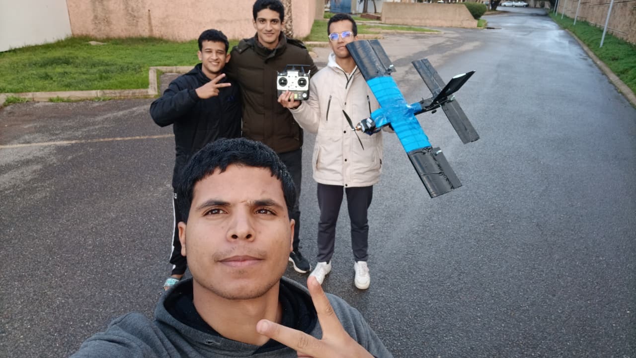
Full design-build-fly cycle of a fixed-wing surveillance UAV: constraint analysis, airfoil selection (NACA 4418), aerodynamic simulation in XFLR5 across Re = 109k-329k, 6-DOF MATLAB/Simulink flight model coupled with FlightGear, and physical fabrication from XPS foam. The aircraft achieved stable simulated flight with LQR longitudinal control. Key design outputs: Payload = 700 g, wingspan = 1 m, chord = 0.2 m, AR = 5, cruise speed = 34 m/s, max speed = 42 m/s, stall speed = 7 m/s, take off distance = 18 m, service ceiling = 3 km.
My Contributions
In a 4-person team, I owned the aerodynamic design (preliminary wing and horizontal stabilizer) and the numerical flight simulation using Python and MATLAB/Simulink coupled with FlightGear for visualisation.
Preliminary Wing Design
Performed constraint analysis and matching diagram to determine wing loading and power loading. Selected NACA 4418 airfoil and defined all wing geometric parameters.
Horizontal Stabilizer Design
Sized the horizontal tail using volume coefficient method, set moment arm to ensure adequate static margin and pitch authority.
XFLR5 Aerodynamic Analysis
Performed full aerodynamic analysis of the NACA 4418 across multiple Reynolds number regimes using XFLR5.
6-DOF MATLAB/Simulink Model
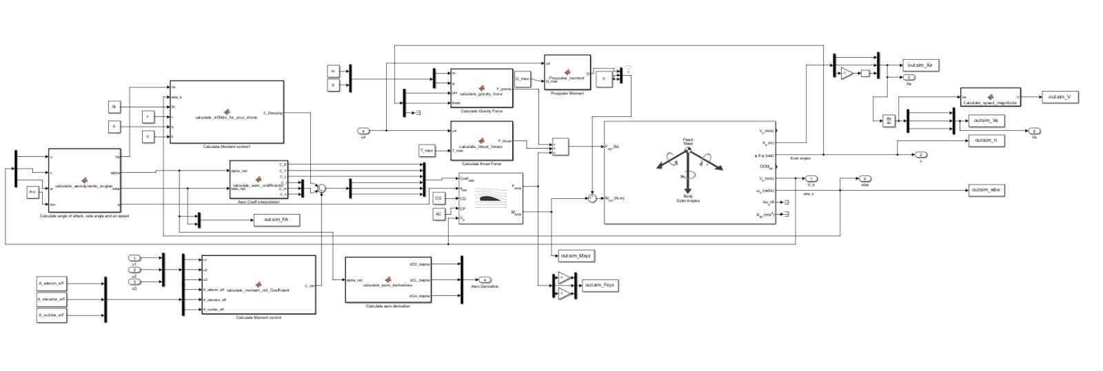
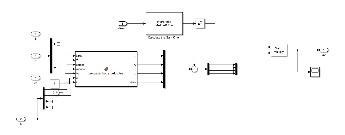
Built a complete nonlinear 6-DOF rigid body model in Simulink with aerodynamic look-up tables, propulsion model, and LQR pitch control.
FlightGear Coupling & Mission Simulation
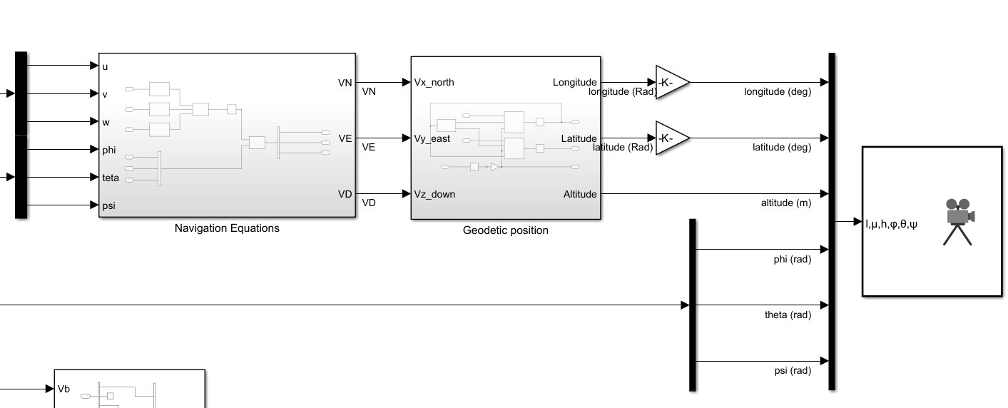
Configured UDP data exchange between Simulink and FlightGear for real-time 3D visualization of the drone's mission profile.
Development Methodology
Step 1: Mission Requirements & Constraint Analysis
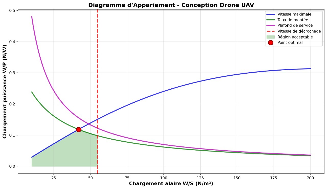
Defined the surveillance mission profile and translated requirements into aerodynamic constraints. Plotted a matching diagram to identify the optimal wing loading and power loading design point.
Step 2: Airfoil Selection & Wing Sizing
Compared candidate airfoil profiles and selected NACA 4418 for its high-lift, low-speed performance. Performed XFLR5 analysis across multiple Reynolds number regimes and defined the wing geometry.
Step 3: Empennage Design & Stability Analysis
Sized horizontal and vertical stabilizers using volume coefficient methods. Verified longitudinal and directional stability through XFLR5 full-aircraft analysis.
Step 4: Flight Dynamics Modeling & LQR Control
Built a nonlinear 6-DOF rigid body model in MATLAB/Simulink with aerodynamic look-up tables from XFLR5. Linearized longitudinal dynamics and designed an LQR controller for pitch attitude hold.
Step 5: FlightGear Simulation & Mission Validation
Coupled the Simulink model to FlightGear via UDP for real-time 3D visualization. Simulated the complete surveillance mission and validated flight controller performance.
Step 6: Physical Fabrication & Ground Testing
Fabricated the airframe from XPS foam using hot-wire cutting. Assembled all avionics and propulsion components, then conducted ground vibration tests and CG balance checks.
Aerodynamic Design & Analysis
Constraint Analysis & Wing Sizing
Matching diagram analysis (stall speed, max speed, climb rate, service ceiling constraints) identified the optimal design point: W/S = 41.95 N/m², W/P = 0.12 N/W. From MTOW = 800 g, this yields wing area S = 0.2 m², span b = 1 m, mean chord c = 0.2 m, AR = 5, and required motor power P = 71.32 W. Calculated performance: Vs = 7 m/s, VC = 34 m/s, Vmax = 42 m/s, ROC = 5 m/s, service ceiling = 3 km.
Airfoil: NACA 4418
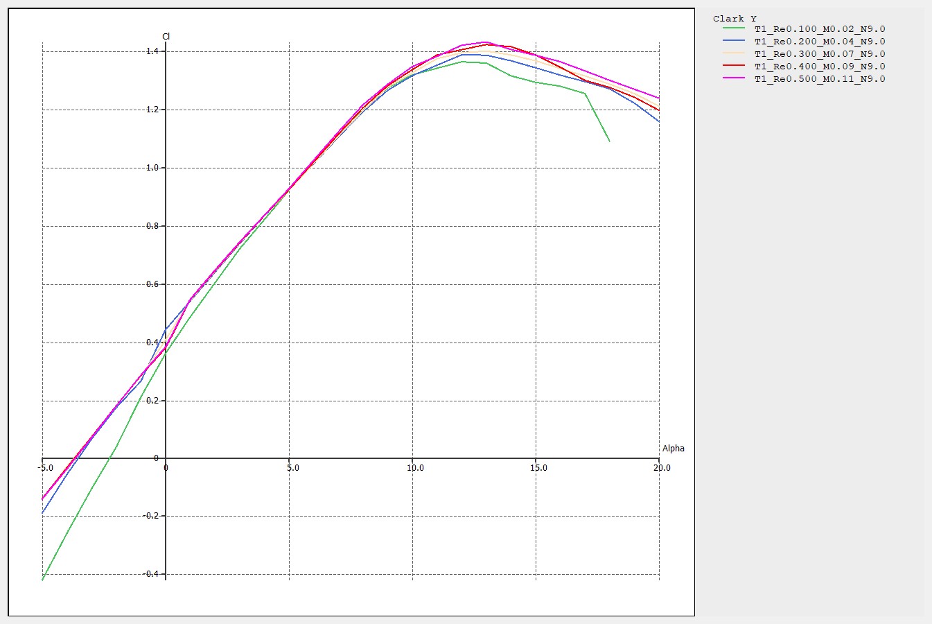
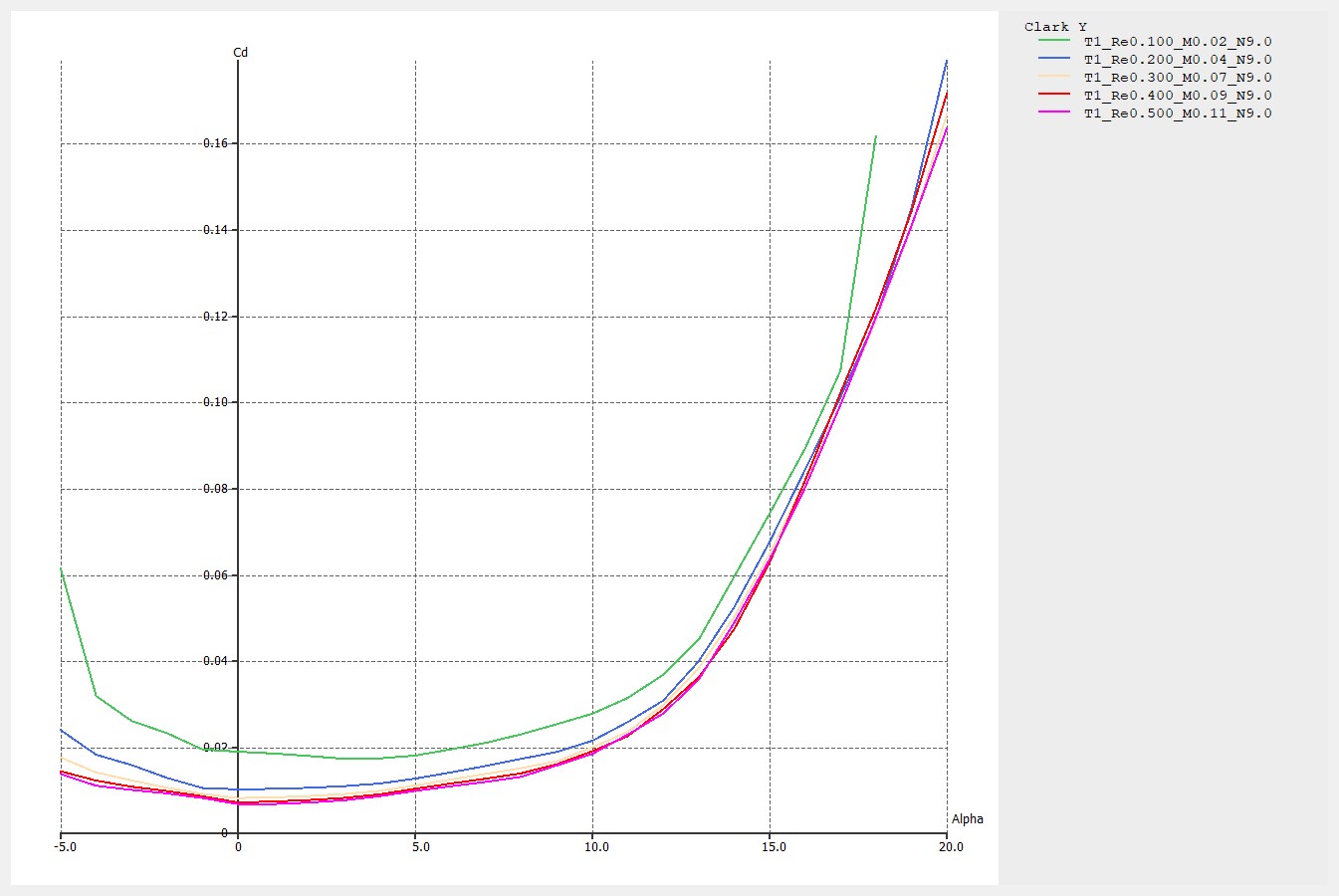
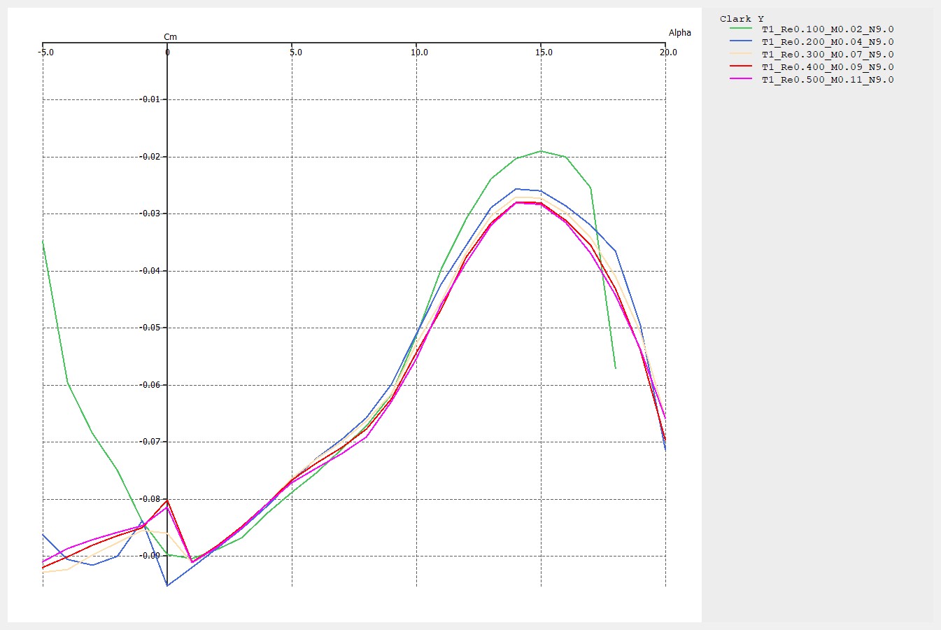
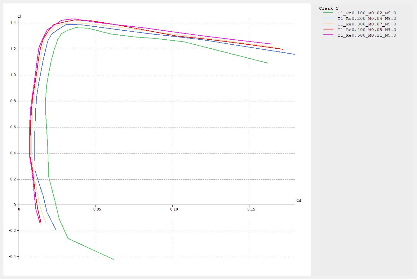
The NACA 4418 profile was selected for its high-lift, low-speed performance characteristics. Geometry: maximum camber 4% at 40% chord, maximum thickness 18% at 30% chord, aerodynamic center at 25% chord. XFLR5 analysis across Re = 109k–329k (V = 8–24 m/s) confirmed CL,max = 1.4 at α = 13°. CD,min = 0.008. Zero-lift pitching moment Cm₀ = −0.06.
Wing Geometric Parameters
| Parameter | Symbol | Value |
|---|---|---|
| Wingspan | b | 1 m |
| Mean Chord | c | 0.2 m |
| Wing Area | S | 0.2 m² |
| Aspect Ratio | AR | 5 |
| Taper Ratio | λ | 1.0 (rectangular) |
| Sweep Angle | Λ | 0° |
| Wing Incidence | iw | 0° |
| Wing Position | High-wing |
Empennage Design
Horizontal Stabilizer
- Volume Coeff. V̄H: 0.50
- Area: 0.12 m² lH = 0.85 m
Vertical Stabilizer
- Volume Coeff. V̄V: 0.04
- Area: 0.08 m² lV = 0.85 m
XFLR5 Aerodynamic Analysis
XFLR5 analysis of the NACA 4418 profile was performed across five Reynolds number regimes corresponding to the drone's operational speed range. The results confirmed the airfoil's suitability for low-speed surveillance missions with CL,max = 1.4 at α = 13°. Stability derivatives were exported for use in the MATLAB/Simulink 6-DOF model.
| Speed (m/s) | Reynolds Number |
|---|---|
| 8 | 109,000 |
| 12 | 164,000 |
| 16 | 219,000 |
| 20 | 274,000 |
| 24 | 329,000 |
Flight Control System
6-DOF Model & LQR Design
Longitudinal dynamics were linearized at cruise trim (V = 18 m/s, h = 100 m), producing a 4th-order state-space model (u, w, q, θ). LQR gains were computed with Q = diag([1, 1, 10, 50]) and R = diag([0.1, 1]) to prioritize pitch attitude hold while limiting elevator saturation.
FlightGear Mission Simulation
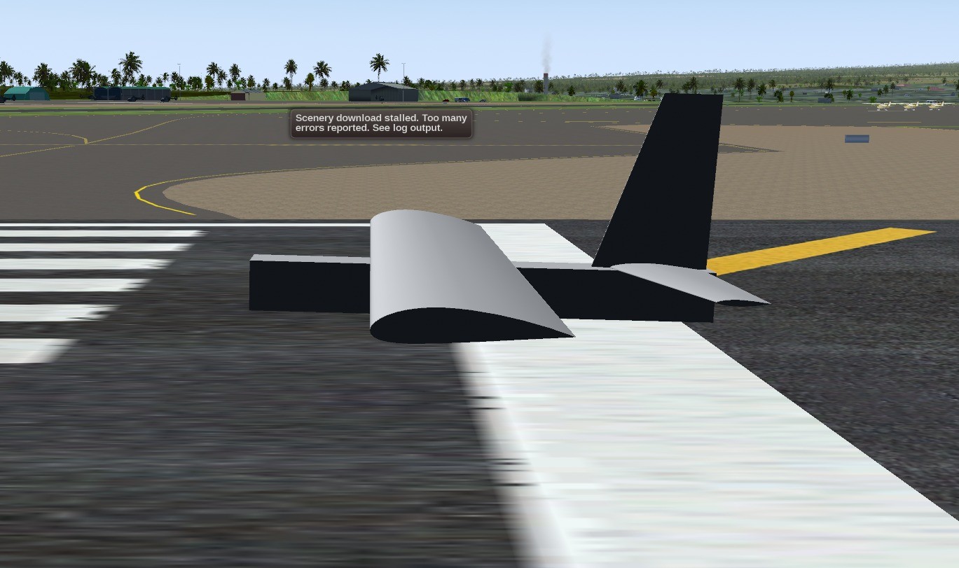
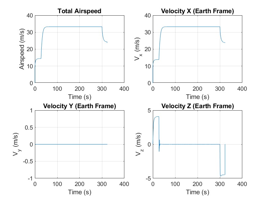
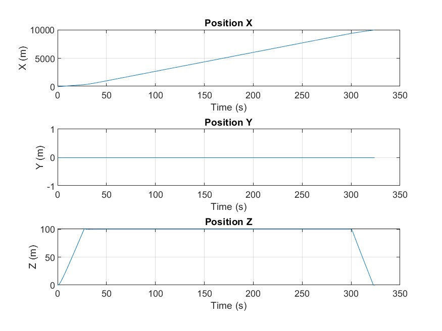
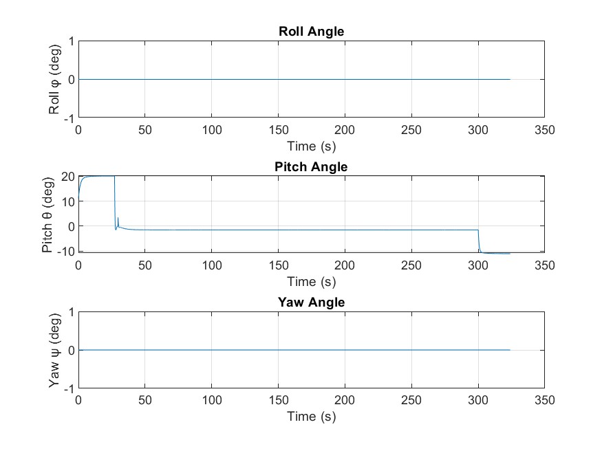
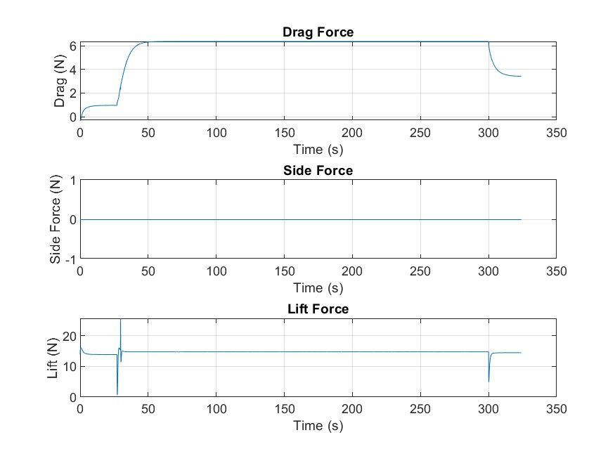
A complete mission simulation was performed in MATLAB/Simulink to validate the drone's trajectory along the defined surveillance profile. During the climb phase, the drone ascended with a pitch angle of 20° and a climb rate of 5 m/s at a total velocity of 15 m/s. Upon reaching the cruise altitude of 100 m, the drone maintained level flight at a cruise speed of 34 m/s, with capability to reach 42 m/s. After 5 minutes of cruise, the descent phase began with a pitch angle of −10° and a rate of descent of 5 m/s at a total airspeed of 25 m/s. The drone completed the 10 km mission in 320 seconds with an average speed of 112 km/h.
Simulation Results
The simulation was run across three distinct flight phases (climb, cruise, descent), covering a total distance of 10 km with a maximum speed of 42 m/s. The following plots show the drone's velocity, position, attitude, and aerodynamic forces throughout the mission.
Complete Flight Phase Performance Summary
| Parameter | Climb | Cruise | Descent |
|---|---|---|---|
| Climb/descent rate (m/s) | 5.0 | −5.0 | |
| Pitch angle (°) | 20 | 0 | −10 |
| Parameter | Value |
|---|---|
| Cruise speed (m/s) | 34 |
| Maximum speed (m/s) | 42 |
| Take-off distance (m) | 18 |
| Payload (g) | 700 |
CAD Design & Fabrication
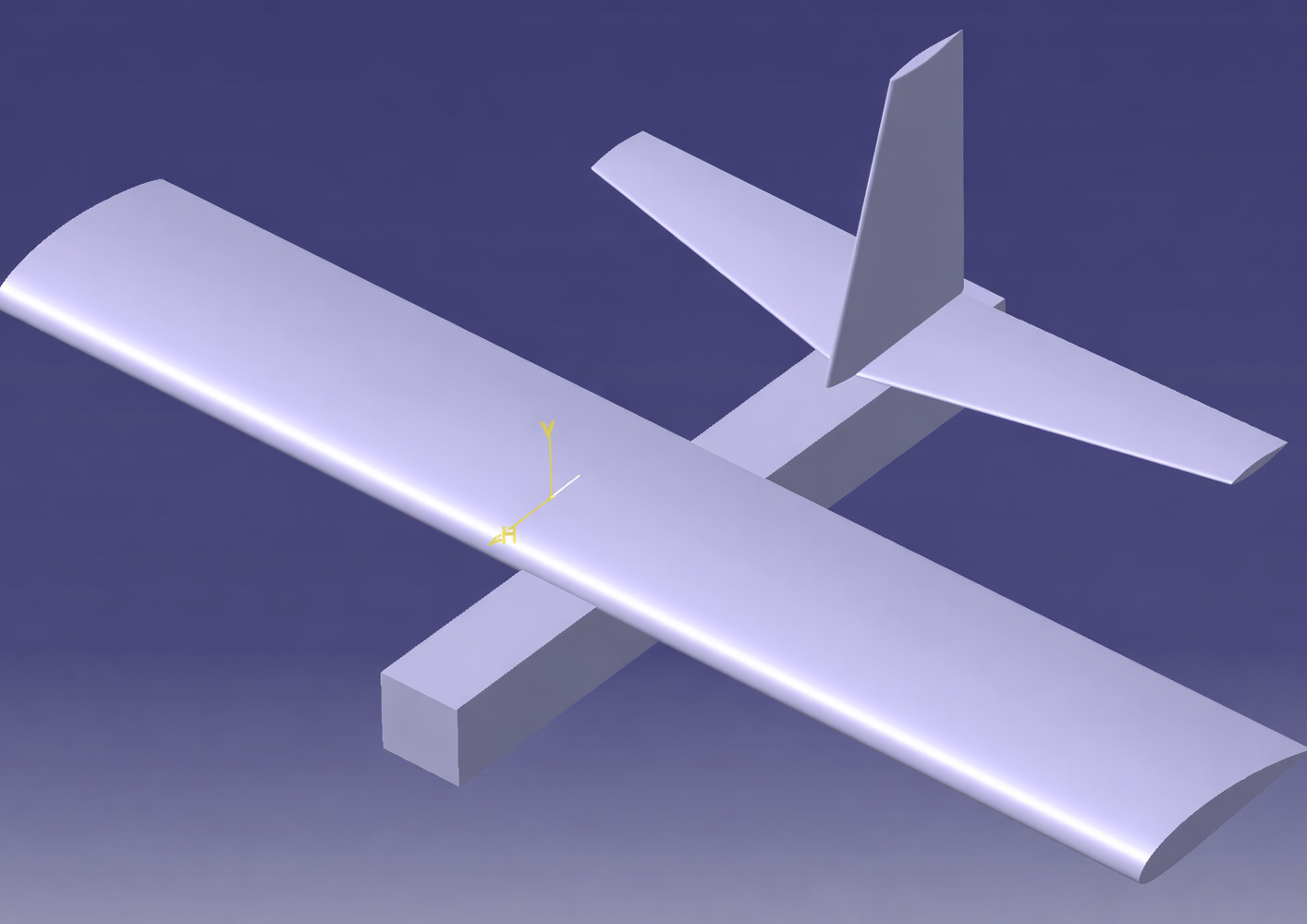
Complete CATIA V5 assembly model drove the manufacturing blueprint. Wings were hot-wire cut from EPS foam following the NACA 4418 profile. Fuselage and stabilizer were also built using EPS foam. Stabilizers were also hot-wire cut following their NACA profile.
Build Specs
- Drone Empty weight: 800 g
- Battery: 4S 5000 mAh LiPo
- Motor: 1050 KV brushless, 250W
- Propeller: 10×4.7 APC
Testing & Results
Ground Testing
Static thrust measured at 6.8 N (full throttle), matching the propulsion model within 4%. Control surface deflections verified: aileron ±18°, elevator ±15°, rudder ±20°. All servos responded within 80 ms of RC command.
Flight Testing Outcomes
What Worked / What Didn't
- Aerodynamics: Glide ratio in hand-toss test ≈ 9 within 15% of XFLR5 prediction at low power
- Stability: Aircraft showed positive pitch stability; recovered from ±10° perturbations without input
- CG Sensitivity: 3 mm CG shift aft pushed aircraft toward phugoid instability, highlighted tolerance need
- Launch: Hand-launch at < 12 m/s proved insufficient; catapult launch recommended for next iteration
- Crash Analysis: Right wing tip strike on landing insufficient dihedral effect at low speed; Γ increased to 5° for v2
Outcomes & Future Work
Key Achievements
- Full design cycle completed in 4 months
- Simulated LQR control meets all stability specs
- FlightGear mission demonstrated profile mission hold
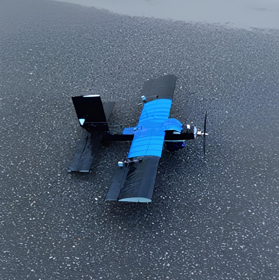
- Physical drone built and ground-validated
Next Iteration
- Increase dihedral to Γ = 5° for low-speed roll stability
- Add catapult launch rail for controlled hand-off speed
- Integrate Pixhawk autopilot for autonomous waypoint nav
- Wind tunnel validation of XFLR5 polar predictions