Academic Project

Fluid-Structure Interaction of a Drone Wing

Duration 2 days
Team 2 Members
Tools ANSYS Workbench, Fluent, Mechanical
70 m/s
Flow Velocity
15°
Angle of Attack
1.36
Lift Coefficient
0.22
Drag Coefficient

One-Way Coupled FSI Analysis

A numerical study of a drone wing under aerodynamic loading using a one-way coupled Fluid-Structure Interaction approach in ANSYS Workbench. The CFD simulation in ANSYS Fluent determined the pressure distribution around the wing using the k-ω SST turbulence model. These aerodynamic loads were then transferred to ANSYS Mechanical for a static structural analysis, evaluating deformations and von Mises stresses in an aluminum alloy wing. The study demonstrated the full FSI simulation chain while identifying optimization opportunities for realistic lightweight wing structures.

Contributions

Co-led the complete FSI simulation workflow, from CAD preparation to final structural interpretation.

CFD Simulation Setup

Created fluid domain enclosure, defined boundary conditions (velocity inlet, pressure outlet, wall), and configured k-ω SST turbulence model in ANSYS Fluent.

Meshing Strategy

Designed dual-resolution mesh: fine body sizing (5×10⁻³ m) near wing, coarser face sizing (1×10⁻² m) at boundaries with quadratic tetrahedra for improved accuracy.

FSI Coupling

Configured one-way coupling workflow in ANSYS Workbench: transferred CFD pressure loads to Mechanical via imported pressure for structural analysis.

Structural Analysis

Set up static structural analysis with aluminum alloy properties, fixed root boundary condition, and evaluated von Mises stress and total deformation fields.

Convergence Monitoring

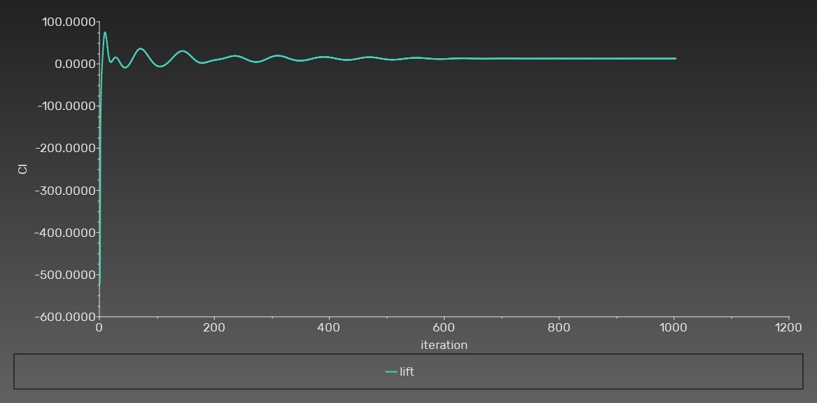
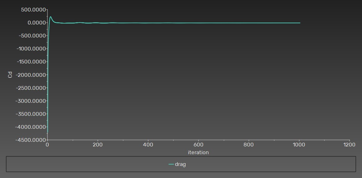
Monitored residuals, outlet pressure/velocity, mass flow rate, and aerodynamic coefficients to validate CFD convergence over 1000 iterations.

Report and Documentation

Authored the comprehensive technical report with governing equations (RANS, Hooke's law, von Mises criterion), results visualization, and engineering interpretation.

FSI Simulation Workflow

The one-way coupled approach transfers aerodynamic pressure from CFD to structural analysis without back-propagation of deformation to the fluid domain.

Step 1 - CAD and Fluid Domain

Wing geometry was modeled in CAD and imported into ANSYS Discovery. An enclosure (bounding box) was created around the wing with sufficient upstream, downstream, and lateral margins to avoid boundary interference on the flow.

Step 2 - Surface Naming

Named selections were defined in Discovery for clean boundary condition assignment: Inlet (all upstream surfaces), Outlet (rear face), and Wall wing (wing surface with no-slip condition).

Step 3 - CFD Meshing

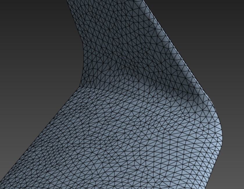
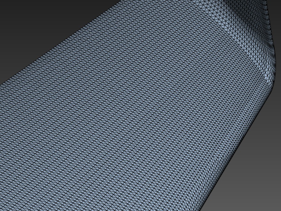
Generated unstructured tetrahedral mesh using Patch Conforming method with quadratic elements. Fine body sizing on the wing for high resolution near surfaces, coarser face sizing on inlet/outlet, and mapped face meshing on selected faces. Progressive transition between refined and coarse zones.

Step 4 - CFD Solution (ANSYS Fluent)

Configured Density-Based solver, steady-state, k-ω SST turbulence model. Velocity inlet with defined angle of attack, pressure outlet at gauge pressure. Standard initialization with sufficient iterations. All residuals converged below target thresholds.

Step 5 - Load Transfer

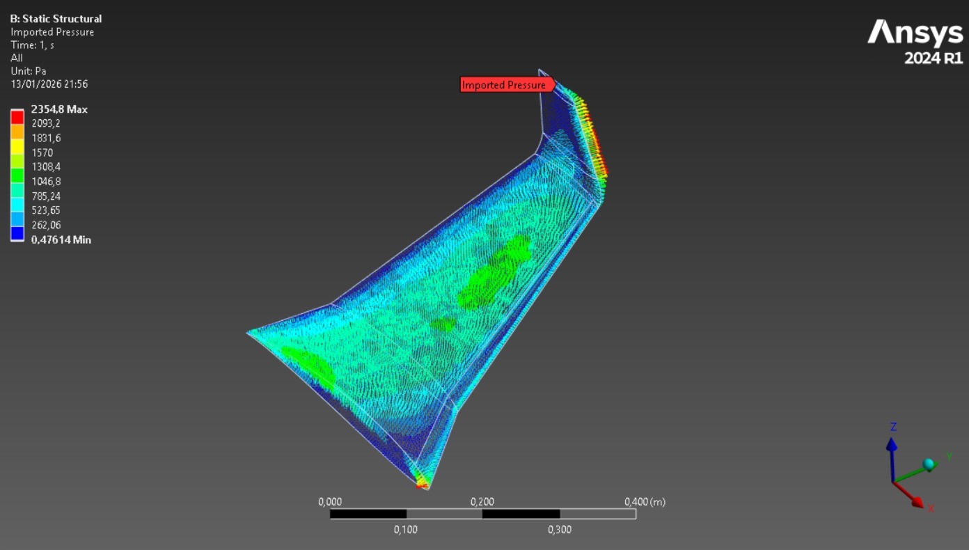
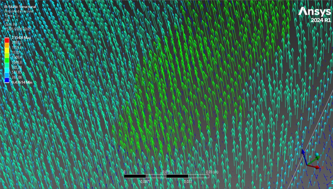
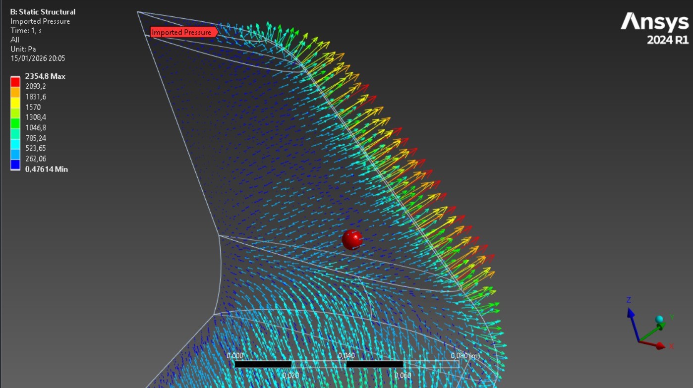
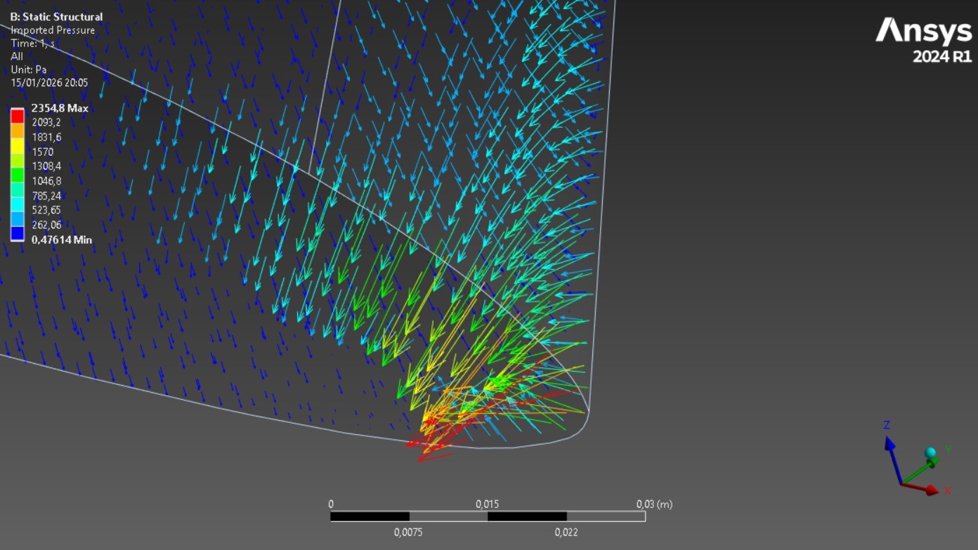
CFD pressure results were transferred to ANSYS Mechanical via 'Imported Pressure' applied on wing faces through the contact region source surface. Pressure vectors verified: upward on main surface (lift), rearward at leading edge (drag), lateral on ailerons.

Step 6 - Structural Analysis (ANSYS Mechanical)

Fluid domain suppressed; wing geometry retained. Aluminum alloy material assigned with standard mechanical properties. Wing root fully clamped (encastrement). Static structural solve using FEM with quadratic tetrahedral elements.

Step 7 - Post-Processing and Interpretation

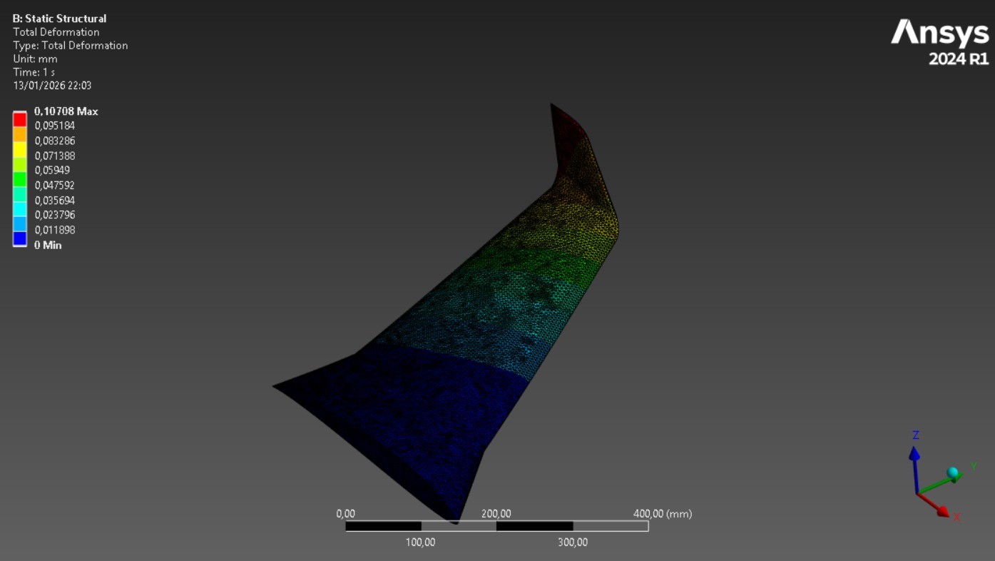
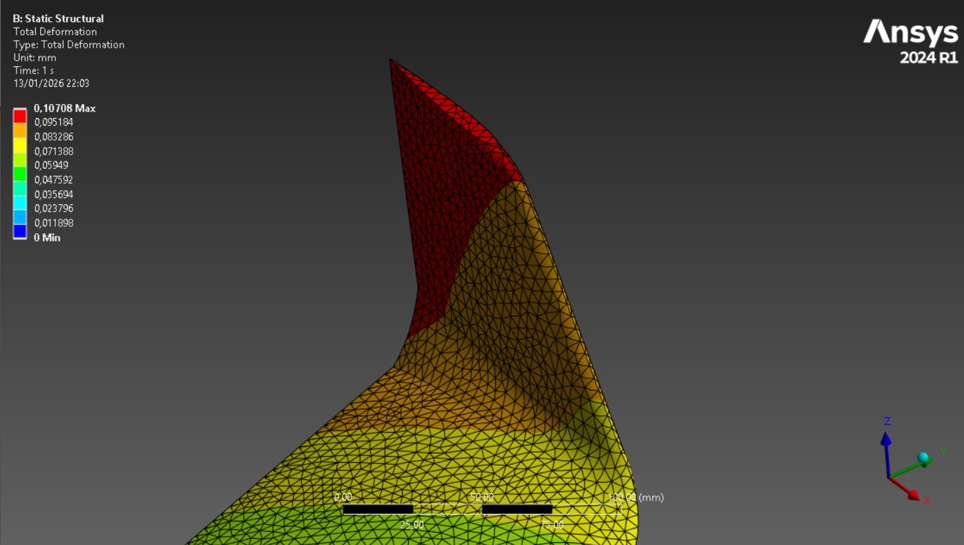
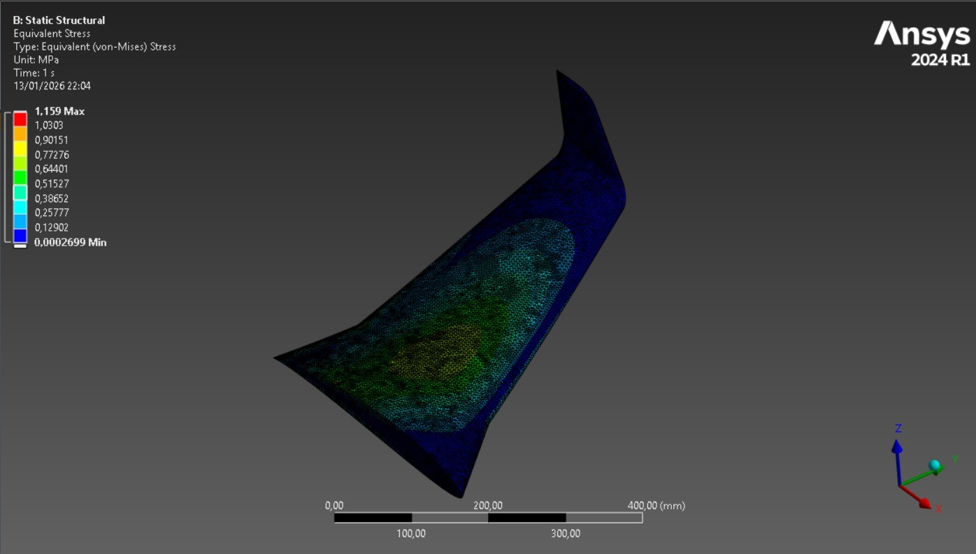
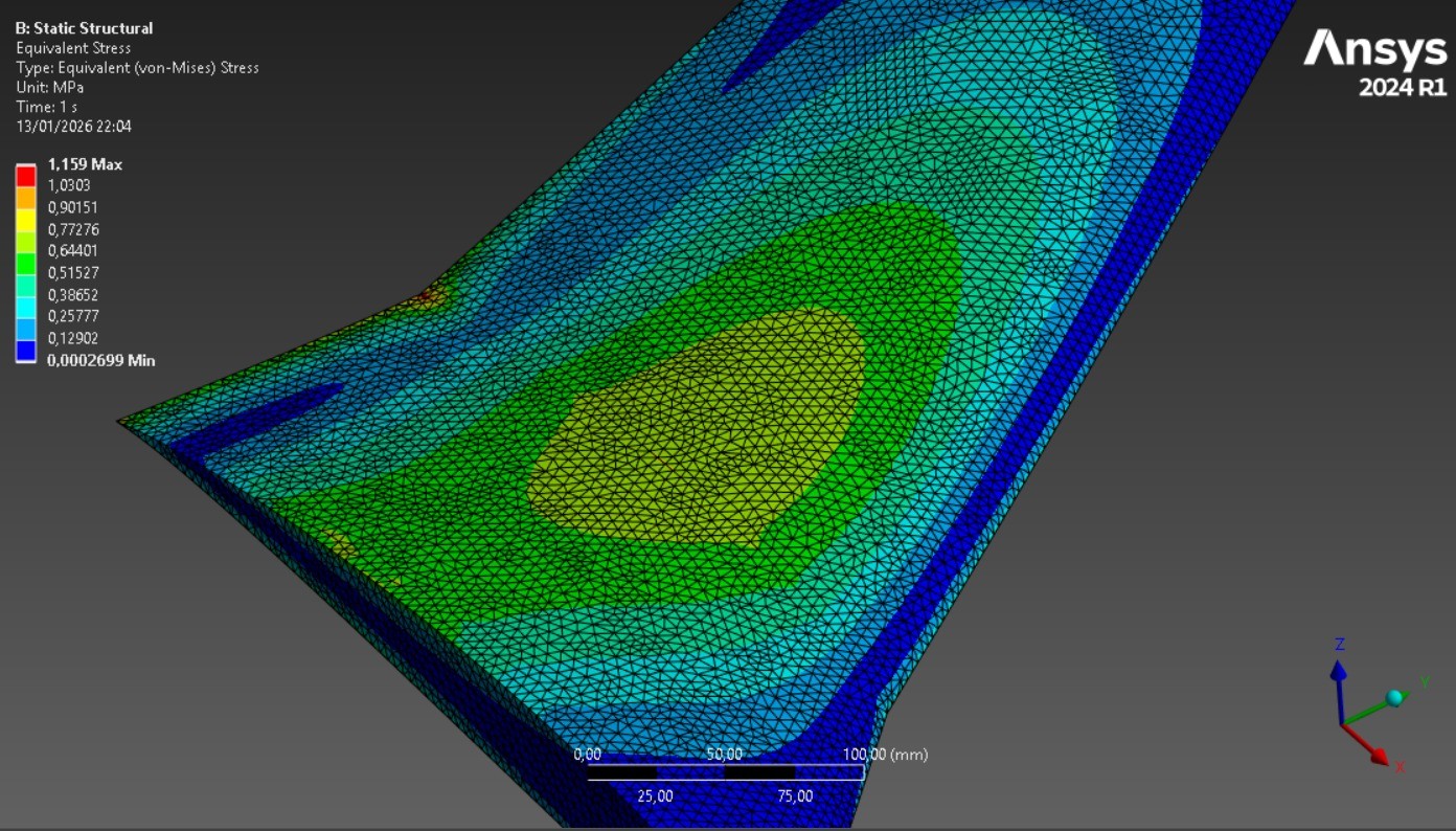
Evaluated total deformation field, von Mises equivalent stress distribution, and safety factor. Maximum deformation at wingtip, maximum stress at root. Identified that solid geometry leads to over-dimensioning - real wings use skin-spar-rib construction for mass optimization.
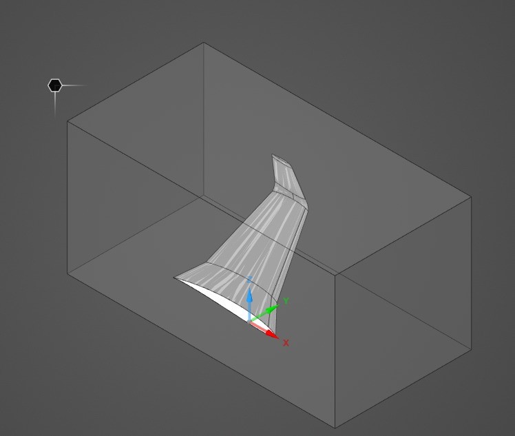
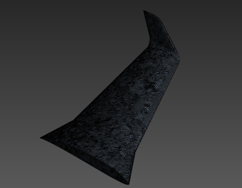
Fluid domain around the wing in ANSYS Discovery
Fluid domain around the wing in Discovery
Mesh zoom showing local refinement near the wing
Mesh zoom near the wing showing local refinement

Aerodynamic Simulation

The RANS-based CFD simulation captured the turbulent airflow around the wing at high angle of attack, providing the pressure field for structural loading.

Solver Configuration

Parameter Value
Solver Type Density-Based
Temporal Regime Steady (stationary)
Velocity Formulation Absolute
Turbulence Model k-ω SST
Fluid Air, ρ = 1.225 kg/m³
Freestream Velocity 70 m/s at 15° AoA
Initialization Standard
Iterations 1000

Convergence

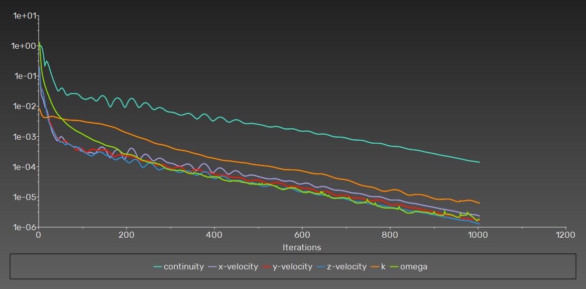
The simulation converged after approximately 2.5 hours of computation. All residuals fell below the 10⁻³ target thresholds:

Residual Target Achieved
Continuity 10⁻³ 1.3872 × 10⁻⁴
Momentum 10⁻³ 1.5770 × 10⁻⁶
Turbulence k 10⁻³ 6.2874 × 10⁻⁶
Turbulence ω 10⁻³ 1.7775 × 10⁻⁶
Residuals evolution vs iterations
Residuals evolution vs. iterations

Convergence of Main Parameters

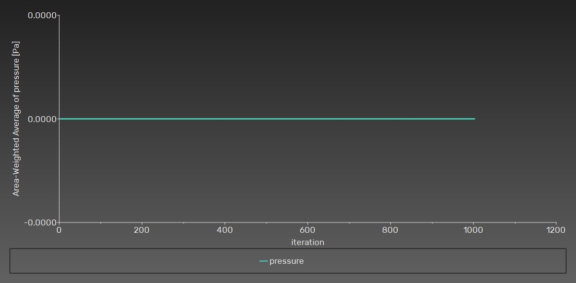
Static pressure convergence at outlet
Static pressure at the outlet
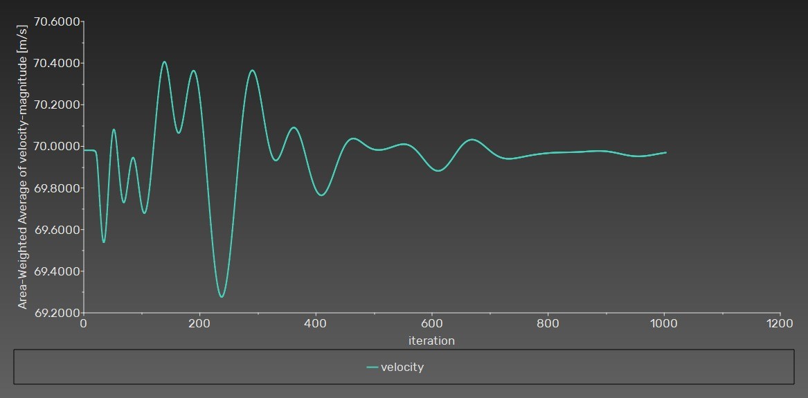
Velocity convergence at outlet
Velocity at the outlet
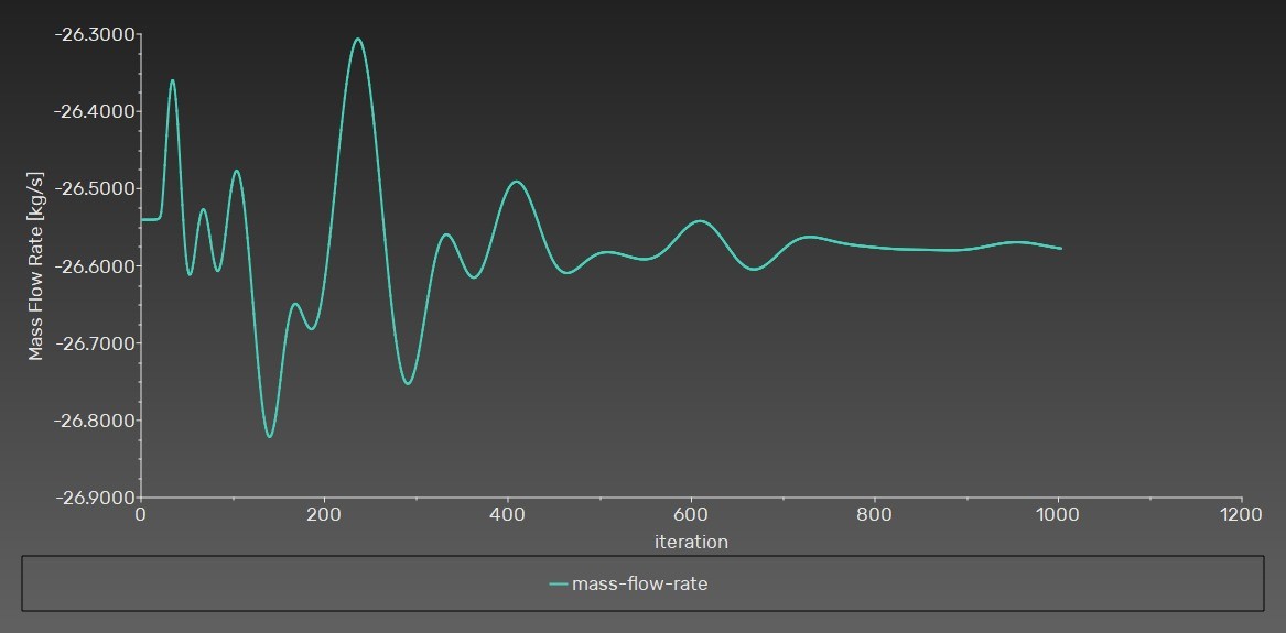
Mass flow rate convergence at outlet
Mass flow rate at the outlet
Lift coefficient convergence
Lift coefficient
Drag coefficient convergence
Convergence of main CFD simulation parameters - Drag coefficient

Pressure Distribution

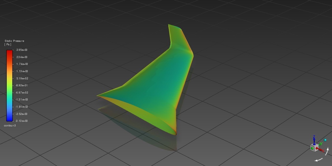
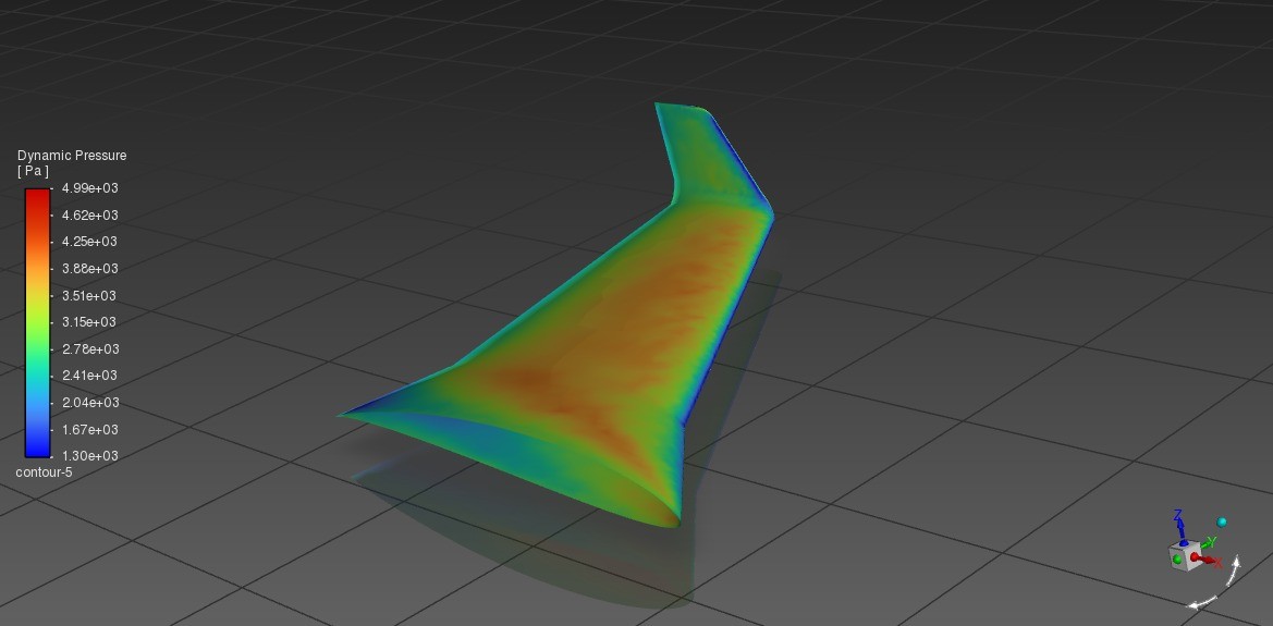
The CFD results show a characteristic pressure distribution for a lifting airfoil at positive incidence, overpressure on the intrados and suction on the extrados. Converged parameters: outlet velocity → 70 m/s, outlet pressure → 0 Pa, mass flow rate → −26.54 kg/s.

−3130 Pa
Min Static Pressure
2950 Pa
Max Static Pressure
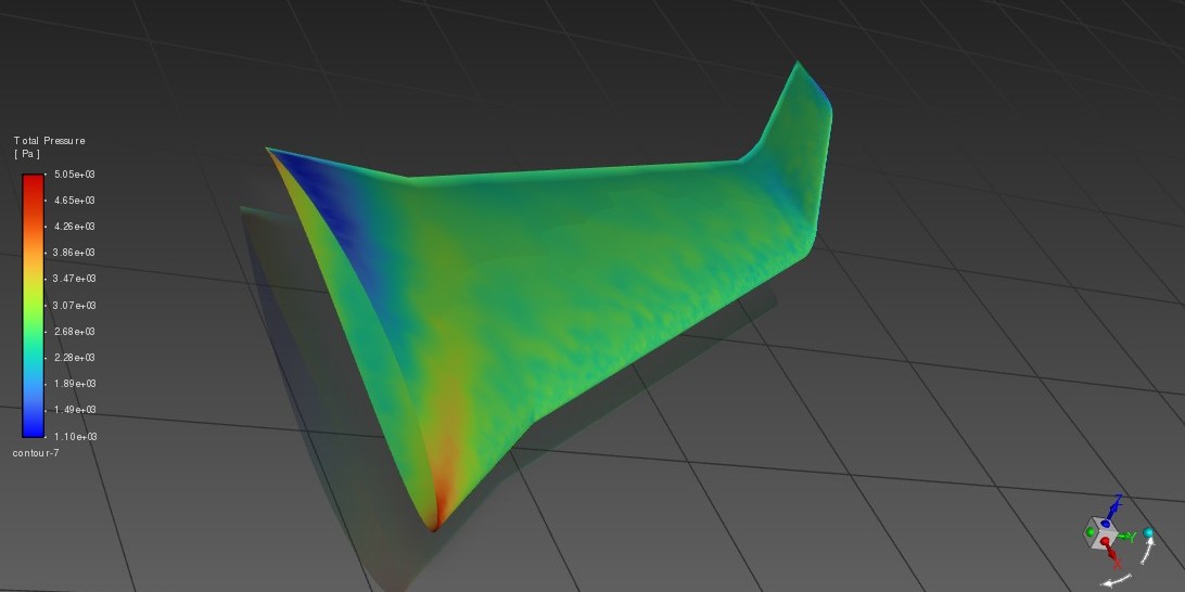
5050 Pa
Max Total Pressure
4990 Pa
Max Dynamic Pressure
Static pressure distribution on the wing
Static pressure
Total pressure distribution on the wing
Total pressure
Dynamic pressure distribution on the wing
Pressure distribution on the wing : Dynamic pressure

Static Structural Response

The imported aerodynamic pressure was applied to an aluminum alloy wing to evaluate deformation and stress under realistic flight loads.

Material Properties - Aluminum Alloy

Property Value Unit
Density (ρ) 2770 kg/m³
Young's Modulus (E) 71 GPa
Poisson's Ratio (ν) 0.33 -
Shear Modulus (G) 26.7 GPa
Tensile Yield Strength 280 MPa
Ultimate Tensile Strength 310 MPa
Compressive Yield Strength 280 MPa

Boundary Conditions

Mesh Configuration

Mesh Method

  • Method: Automatic
  • Element order: Quadratic
  • Element type: Tetrahedra
  • Body sizing: 5 × 10⁻³ m

Load Transfer

  • Type: Imported Pressure
  • CFD surface: contact_region_src
  • Application: Surface Effect
  • Loaded faces: 17
Structural mesh of the wing (full view)
Full wing mesh
Structural mesh zoom
Mesh close-up

Imported Pressure Distribution

Imported pressure on full wing
Imported pressure on the full wing
Zoom on main surface pressure
Zoom on the main surface
Zoom on ailerons pressure
Zoom on the ailerons
Zoom on leading edge pressure
Zoom on the leading edge

Key Findings

The FSI analysis confirmed excellent structural integrity of the solid aluminum wing under aerodynamic loading, while highlighting opportunities for mass optimization.
CL = 1.36
Lift Coefficient
CD = 0.22
Drag Coefficient
0.1 mm
Max Deformation
1.16 MPa
Max von Mises Stress
280 MPa
Yield Strength
241
Safety Factor
Parameter Value Comment
Maximum total deformation 0.1 mm At wingtip (farthest from root)
Maximum von Mises stress 1.16 MPa At wing root (encastrement zone)
Safety factor (vs σy = 280 MPa) 241 Significantly over-dimensioned

Total Deformation

Total deformation of the wing
Zoom on maximum deformation at wingtip
Zoom on maximum deformation

Von Mises Stress

Von Mises equivalent stress on the wing
Von Mises stress on the wing
Zoom on maximum von Mises stress
Zoom on maximum stress

Interpretation

The extremely low stress levels (1.16 MPa vs. 280 MPa yield) and negligible deformation indicate significant over-dimensioning. This is expected because the wing was modeled as a solid aluminum geometry rather than a realistic lightweight structure. In practice, aircraft wings are built with:

The high safety factor suggests that substantial mass reduction is possible without compromising structural integrity, a critical optimization for drone applications where weight directly impacts endurance and performance.

Conclusions and Future Work

Key Achievement

Successfully demonstrated a complete one-way FSI simulation chain in ANSYS Workbench, coupling Fluent CFD aerodynamics with Mechanical structural analysis. The methodology provides a solid baseline for more advanced studies.

Future Perspectives

Two-Way Coupling

Implement bidirectional FSI where structural deformation feeds back to the CFD domain, capturing nonlinear phenomena like flutter and aeroelastic divergence.

Transient Analysis

Study the dynamic response of the wing to rapid load variations, critical for maneuvers and wind gusts during drone operations.

Realistic Structure

Model the wing with internal architecture (skin, ribs, spars) instead of a solid body to achieve realistic mass and stress distributions.

Shape Optimization

Use the FSI results to optimize wing geometry, modifying airfoil profile, span, or chord to improve the lift-to-drag ratio while meeting structural constraints.

Fatigue Analysis

Study the effect of cyclic loading on structural life, particularly important for surveillance drones on extended missions requiring sustained flight loads.

Experimental Validation

Compare numerical results with wind tunnel measurements and static load tests on a physical prototype to validate the simulation models.

Download Project Report