Academic Project

Material Selection for the B787-8 Dreamliner Wing Structure

Duration 1 month
Team 2 Members
Tools CES EduPack, Ashby Method
3
Wing Parts Analyzed
EP-CF70
Primary Structure
Al 7475
Leading Edge
EP-CF70
Trailing Edge
9,210 kg
Estimated Wing Mass

Project Summary

This project focuses on the optimal material selection for the Boeing 787-8 Dreamliner wing structure using Ashby's systematic methodology implemented through CES EduPack software. The wing was decomposed into three essential parts: primary structure, leading edge, and trailing edge (aileron and flap), and each was analyzed independently through performance index derivation, constraint-based filtering, and cost-performance comparison. The results were validated against the actual materials used in the real B787 aircraft.

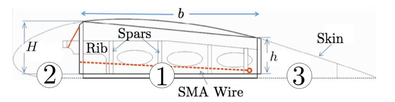
Three essential parts of the wing
Three essential parts of the wing: primary structure, leading edge, and aileron/flap

My Contributions

I was responsible for the entire material selection analysis and the validation against real B787 materials, from deriving performance indices to running CES EduPack simulations and comparing results with actual Boeing data.

Performance Index Derivation

Derived performance indices for all 3 wing parts.

CES EduPack Analysis

Used CES EduPack to generate Ashby charts for each wing part, applying mechanical, thermal, and cost constraints to filter from thousands of materials down to optimal candidates.

Material Comparison

Compared aluminum alloys vs. stainless steels for the leading edge, evaluating performance index, cost per unit performance, machinability, and corrosion resistance.

Validation Against Real B787

Compared selected materials with actual Boeing 787 data, confirming EP-CF70 composites for structure and aluminum alloys for leading edge match real aircraft.

Methodology

Step 1: Wing Decomposition

The wing was treated as a semi-monocoque structure and decomposed into three essential parts: primary structure (main load-bearing), leading edge (impact protection), and aileron/flap (control surfaces). Each part has different functional requirements and loading conditions.

Step 2: Geometry Simplification

Each wing part was simplified into an equivalent structural element: the primary structure as a cantilever beam with hollow rectangular cross-section, the leading edge as a half-tube, and the aileron as a triangular cantilever beam. These simplifications enabled analytical derivation of performance indices.

Step 3: Performance Index Derivation

For each wing part, the objective function (minimize mass) was expressed in terms of material properties using the constraint equations. Free variables were eliminated to derive material performance indices combining density, Young's modulus, fatigue strength, and fracture toughness as appropriate.

Step 4: CES EduPack Filtering

The derived performance index equations were plotted as iso-performance lines on logarithmic Ashby charts using CES EduPack. Constraints (service temperature ≤ −80°C, thermal expansion limits, minimum fracture toughness) were applied progressively to narrow candidate materials.

Step 5: Material Comparison and Selection

Remaining candidates were compared on performance index, cost per unit performance, machinability, corrosion resistance, and ductility. The AND method was used to combine multiple performance indices for the primary structure.

Step 6: Validation Against Real B787 Data

Selected materials were compared with the actual materials used in the Boeing 787 Dreamliner to validate the methodology. Results showed excellent agreement: composites for structure/trailing edge and aluminum for leading edge.

Main Wing Structure Selection

Geometry and Simplification

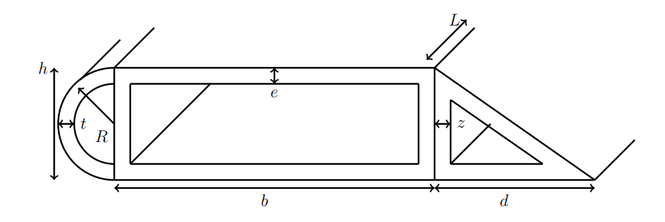
The primary structure carries the bending moment from aerodynamic lift. It was modeled as a cantilever beam with a hollow rectangular cross-section (h = b/4), where the wing root acts as the fixed support (fuselage junction). The distributed load along the wing was approximated as a triangular distribution representing the combined effect of lift and self-weight.
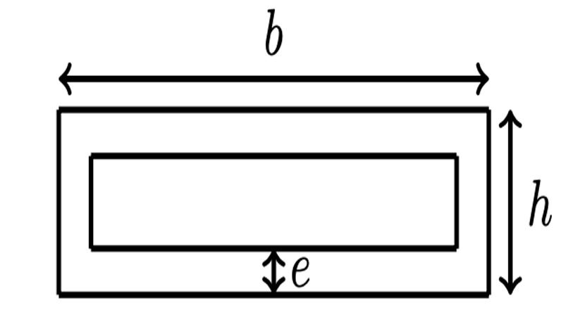
Simplified primary wing structure geometry
Simplified primary wing structure geometry: cantilever beam model

Performance Indices

Two mechanical constraints were derived, fatigue resistance and stiffness, leading to two performance indices combined using the AND method with equal weighting (m₁ = ½):

Final Performance Index Expression: Primary Structure

Using the AND method with base b as free variable:

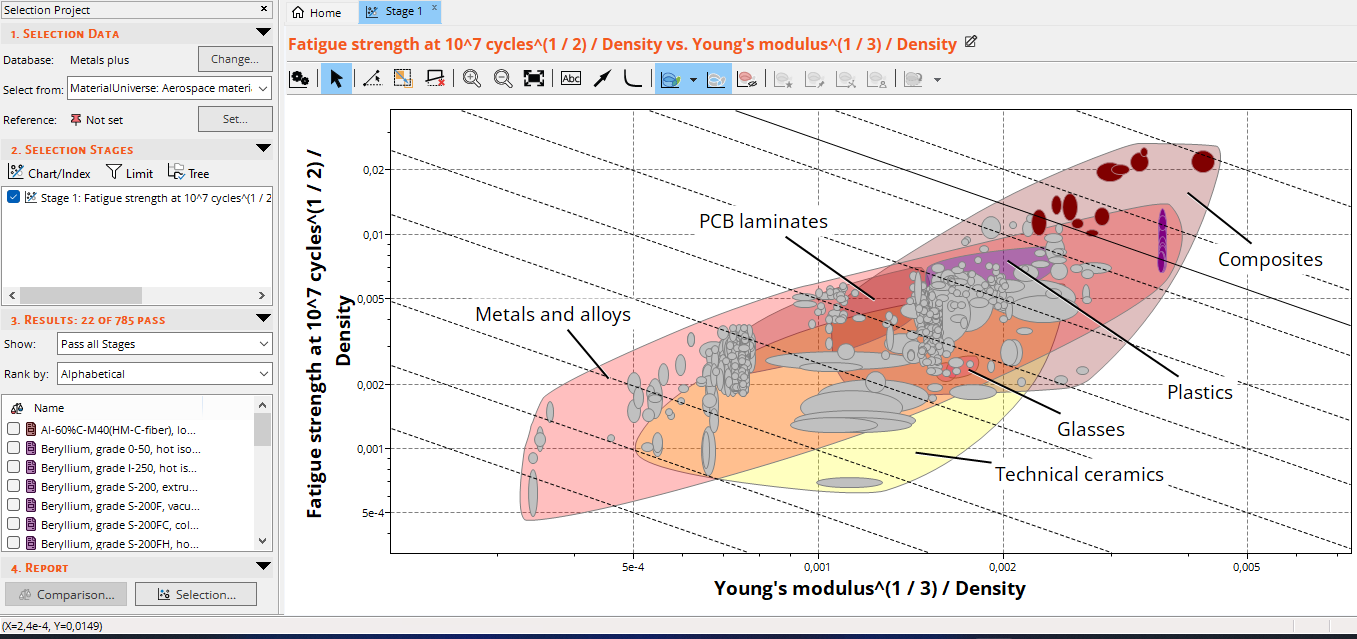
log(σf½ / ρ) = −log(E⅓ / ρ) + 2·log(W*)

Where W₁ = σf½/ρ (fatigue index) and W₂ = E⅓/ρ (stiffness index), combined into the iso-performance line: y = −x + p

Constraint Limits

Constraint Limit
Maximum thermal expansion α ≤ 10⁻⁶ µstrain/°C
Minimum fracture toughness Kc ≥ 30 MPa·m½
Minimum service temperature ≤ −80°C

CES EduPack Results

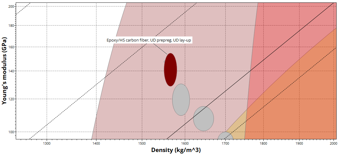
CES results without constraints
CES results without constraints : composites and alloys dominate
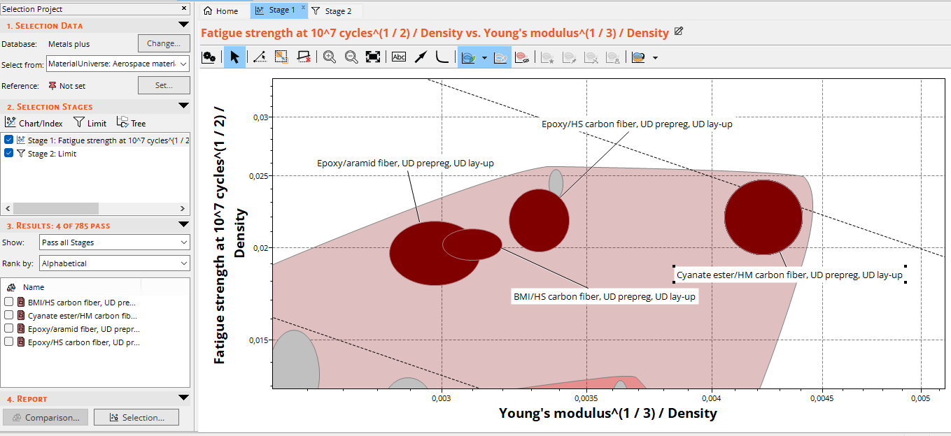
CES results with constraints — zoomed view
CES results with constraints : zoomed view on remaining candidates

Candidate Material Properties

Property BMI-CF65 Cyanate-CF65 EP-RF50 EP-CF70
Density (kg/m³) 1570–1610 1620–1670 1380 1550–1580
Young's Modulus (GPa) 110–130 299–376 60–80 129–154
Yield Strength (MPa) 1710–1740 1890–2530 1100–1380 1740–2170
Fatigue Strength 10⁷ cycles (MPa) 940–1130 1040–1650 605–897 959–1410
Fracture Toughness (MPa·m½) 56.9–73.9 48.3–59 56.3–68.8 60.2–73.5
Min Service Temp (°C) −67 to −47 −51 to −31 −48 to −28 −123 to −73
Thermal Expansion (µstrain/°C) −0.17 −1.6 −0.83 −0.6
Price (EUR/kg) 89.2–107 196–219 44.6–73.4 34.9–38.8

At the B787's maximum cruising altitude of 43,100 ft (~13,137 m), the standard ISA temperature is approximately −56.5°C, but can drop to −70°C or even −80°C in polar/winter conditions. This eliminates BMI-CF65, Cyanate-CF65, and EP-RF50, leaving only EP-CF70.

Selected Material: EP-CF70

Property Value
Fatigue Strength σf (MPa) 959–1410
Young's Modulus E (GPa) 129–154
Yield Strength Re (MPa) 1740–2170
Price (EUR/kg) 34.9–38.8
Density ρ (kg/m³) 1550–1580
Fracture Toughness Kc (MPa·m½) 60.2–73.5
Thermal Expansion α (µstrain/°C) −0.6
Min Service Temperature (°C) −123 to −73
Performance Index P (N·m/kg) 7.69–7.95
Cost/Performance C/P (EUR/N·m) 4.38–5.04

Leading Edge Material Selection

Geometry and Simplification

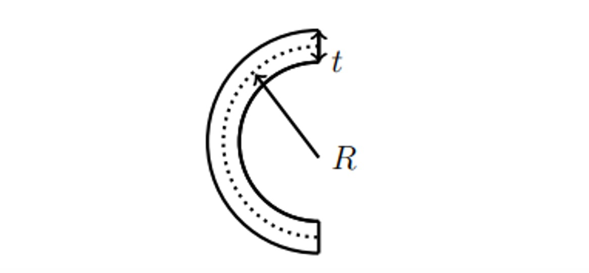
The leading edge was modeled as a half-tube with mean radius R and thickness t, where 2R + t = h (the total height matching the primary structure). Its primary function is impact protection, not bending, requiring high resilience Gc related to fracture toughness Kc.

Simplified leading edge geometry
Simplified leading edge geometry : half-tube model

Performance Index

Final Performance Index Expression: Leading Edge

Since Kc dominates (squared) over E in the resilience expression, but E must not be too high (brittle), the performance index is:

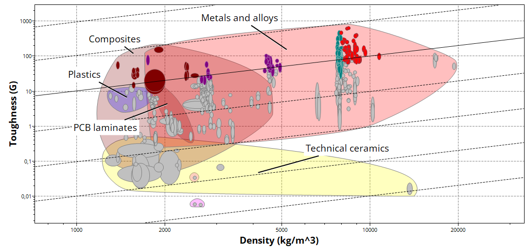
max(W) = max(Kc² / (E · ρ))

Logarithmic form: log(Kc) = ½·log(E) + ½·log(W·ρ)

Constraint Limits

Constraint Limit
Price ≤ 7 EUR/kg
Young's Modulus E ≤ 200 GPa
Yield Strength Re ≥ 400 MPa
Min Service Temperature ≤ −80°C
Thermal Expansion α ≤ 30 × 10⁻⁶ /K
Fracture Toughness Kc ≥ 40 MPa·m½

CES EduPack Results

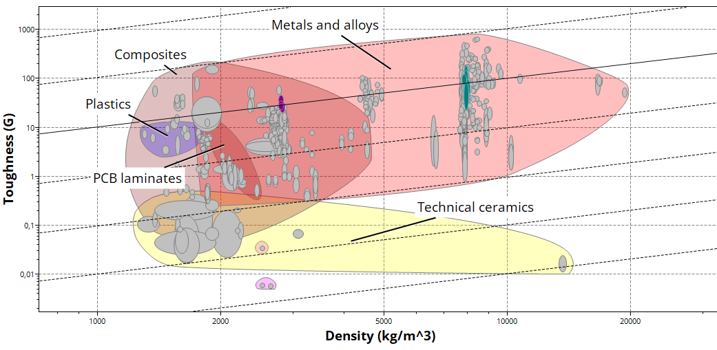
Leading edge results without constraints
Leading edge results with constraints
Leading edge results with constraints applied
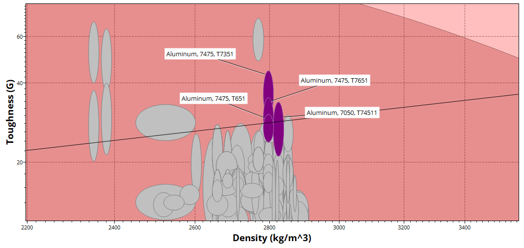
Aluminum alloys — zoomed view
Aluminum alloys : zoomed view of remaining candidates
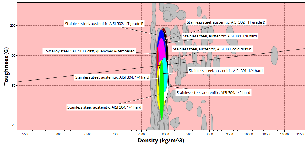
Stainless steels — zoomed view
Stainless steels : zoomed view of remaining candidates

Aluminum Alloys vs. Stainless Steels

Property Aluminum Alloys Stainless Steels
Density ρ (kg/m³) 2780–2840 7810–8060
Young's Modulus E (GPa) 70–74.6 186–205
Fracture Toughness Kc (MPa·m½) 38.9–57.1 62–209
Thermal Expansion α (°K⁻¹) 24–24.6 10.6–18
Fatigue Strength σf (MPa) 130–235 240–753
Price (EUR/kg) 5.41–7.51 1.28–6.52
Resilience Gc (kJ/m²) 21.1–44.5 22.6–189

Performance Index Comparison

Material Group P (J·m/kg) Pavg C/P (€/J·m) Cavg/Pavg
Aluminum Alloys 0.87–1.2 1.03 4.5–8.63 6.27
Stainless Steels 0.44–1.38 0.91 0.92–14.81 4.28

Although some stainless steels achieve a higher maximum performance index (1.38 vs 1.2), their average is lower (0.91 vs 1.03), and cost per unit performance is nearly double. Combined with aluminum's superior machinability and formability for complex leading edge geometries, aluminum alloys were selected.

Aluminum Alloy Candidates

Property Al 7050-T74511 Al 7475-T651 Al 7475-T7351 Al 7475-T7651
Density (kg/m³) 2810–2840 2780–2810 2780–2810 2780–2810
Young's Modulus (GPa) 71–74.6 70–73.6 71–74.6 70–73.6
Yield Strength (MPa) 372–434 462–511 345–427 407–450
Fatigue Strength (MPa) 130–150 205–235 205–235 205–235
Fracture Toughness (MPa·m½) 38.9–49.9 41.4–46.7 46.4–57.1 42.2–50.3
P (J·m/kg) 0.87–1.08 1.02–1.03 1.02–1.2 0.94–1.1
C/P (€/J·m) 5.07–8.63 5.25–7.3 4.5–7.3 4.91–7.92

Aluminum 7475-T7351 surpasses all other candidates across all six comparison criteria, highest fracture toughness, best performance index, and lowest cost per unit performance.

Selected Material: Aluminum 7475-T7351

Property Value
Fatigue Strength σf (MPa) 205–235
Young's Modulus E (GPa) 71–74.6
Yield Strength Re (MPa) 345–427
Price (EUR/kg) 5.41–7.45
Density ρ (kg/m³) 2780–2810
Fracture Toughness Kc (MPa·m½) 46.4–57.1
Thermal Expansion α (µstrain/°C) 23.4–24.6
Min Service Temperature (°C) −273
Performance Index P (J·m/kg) 1.02–1.2
Cost/Performance C/P (€/J·m) 4.5–7.3

Aileron and Flap Material Selection

Geometry and Simplification

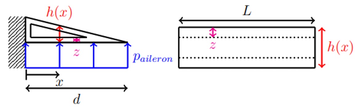
The aileron was modeled as a triangular cantilever beam of length d, fixed to the primary structure. The cross-section varies along the span with average height h/2. The aileron's primary role is flight control (pitch and roll), requiring high stiffness to maintain stable trajectories during aerodynamic loading.

Simplified aileron and flap geometry
Simplified aileron and flap geometry : triangular cantilever beam model

Performance Index

Final Performance Index Expression: Trailing Edge

The stiffness constraint with L as the free variable (dominant exponent) yields:

max(W) = max(E⅓ / ρ)

Logarithmic form: log(E) = 3·log(ρ) + 3·log(W), giving the iso-performance line: y = 3x + p

Constraint Limits

Constraint Limit
Min Service Temperature ≤ −80°C
Thermal Expansion α ≤ 10⁻⁵ /K
Fracture Toughness Kc ≥ 30 MPa·m½

CES EduPack Results

Without constraints, composites and beryllium alloys dominate. After applying the thermal and toughness constraints, only one material remains: EP-CF70, the same composite selected for the primary structure.

Trailing edge results with constraints — zoomed view
Trailing edge results with constraints, zoomed on EP-CF70 as the sole candidate

Selected Material: EP-CF70

Property Value
Fatigue Strength σf (MPa) 959–1410
Young's Modulus E (GPa) 129–154
Yield Strength Re (MPa) 1740–2170
Price (EUR/kg) 34.9–38.8
Density ρ (kg/m³) 1550–1580
Fracture Toughness Kc (MPa·m½) 60.2–73.5
Thermal Expansion α (µstrain/°C) −0.6
Min Service Temperature (°C) −123 to −73
Performance Index P (√N·m4/3/kg) 0.5–0.53
Cost/Performance C/P (EUR/√N·m4/3) 65.84–77.6

Results and Validation

Final Material Selection Summary

EP-CF70
Primary Structure
Al 7475
Leading Edge
EP-CF70
Aileron and Flap
Wing Part Selected Material Performance Index Key Criteria
Primary Structure EP-CF70 (Carbon Fiber/Epoxy) 7.69–7.95 N·m/kg Fatigue + Stiffness (AND method)
Leading Edge Aluminum 7475-T7351 1.02–1.2 J·m/kg Impact resistance (Kc²/Eρ)
Trailing Edge EP-CF70 (Carbon Fiber/Epoxy) 0.5–0.53 √N·m4/3/kg Stiffness (E⅓/ρ)

Final Simplified Wing Model

Final simplified wing model
Final simplified wing model with material assignments

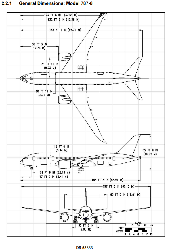
B787-8 Dreamliner Dimensions

B787-8 Dreamliner dimensions
B787-8 Dreamliner dimensions used for mass estimation

Mass Estimation

Using the selected materials and simplified geometry applied to the actual B787-8 dimensions, the estimated mass of a single wing is approximately 9,210 kg. The real wing mass is estimated between 12,500 and 15,000 kg. The difference is attributed to:

  • Material differences: actual B787 also incorporates glass fibers in the wing box
  • Structural components: ribs, stringers, fasteners, and internal systems not modeled
  • Geometry simplification: the real wing has complex 3D curvature not captured by beam models

Validation Against Real B787 Materials

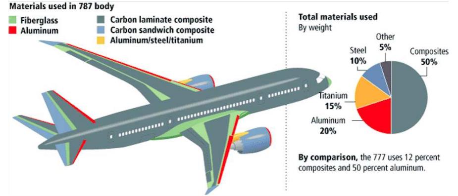
Materials used in B787
Materials used in the Boeing 787: composites, aluminum, titanium, and steel

Validation Results

  • Leading edge: Real B787 uses aluminum alloys, matches our selection of Al 7475-T7351
  • Primary structure: Real B787 uses carbon fiber composites, matches our EP-CF70 (with additional glass fiber in the wing box for cost and vibration damping)
  • Aileron and flap: Real B787 uses composites, matches our EP-CF70 selection

The addition of glass fibers in the real aircraft's wing box is explained by: lower cost, sufficient mechanical properties for moderate-stress zones, improved vibration damping, and enhanced structural safety at the critical wing-fuselage junction.

Conclusions and Takeaways

Key Achievements

  • Systematic material selection using Ashby's method for 3 wing parts
  • Performance indices derived analytically from structural mechanics
  • Results validated against actual Boeing 787 material data
  • EP-CF70 composite confirmed as optimal for structure and control surfaces
  • Aluminum 7475-T7351 identified as best leading edge alloy from 4 candidates

Key Insights

  • Composites (carbon fiber/epoxy) dominate modern aircraft wing design
  • Service temperature (≤ −80°C) is a critical filter eliminating most composites
  • Cost per unit performance is as important as absolute performance index
  • Real aircraft blend glass and carbon fibers for cost-safety optimization
  • Aluminum remains cost-effective for impact-critical applications like leading edges
Download Project Report